
Lighting up the world
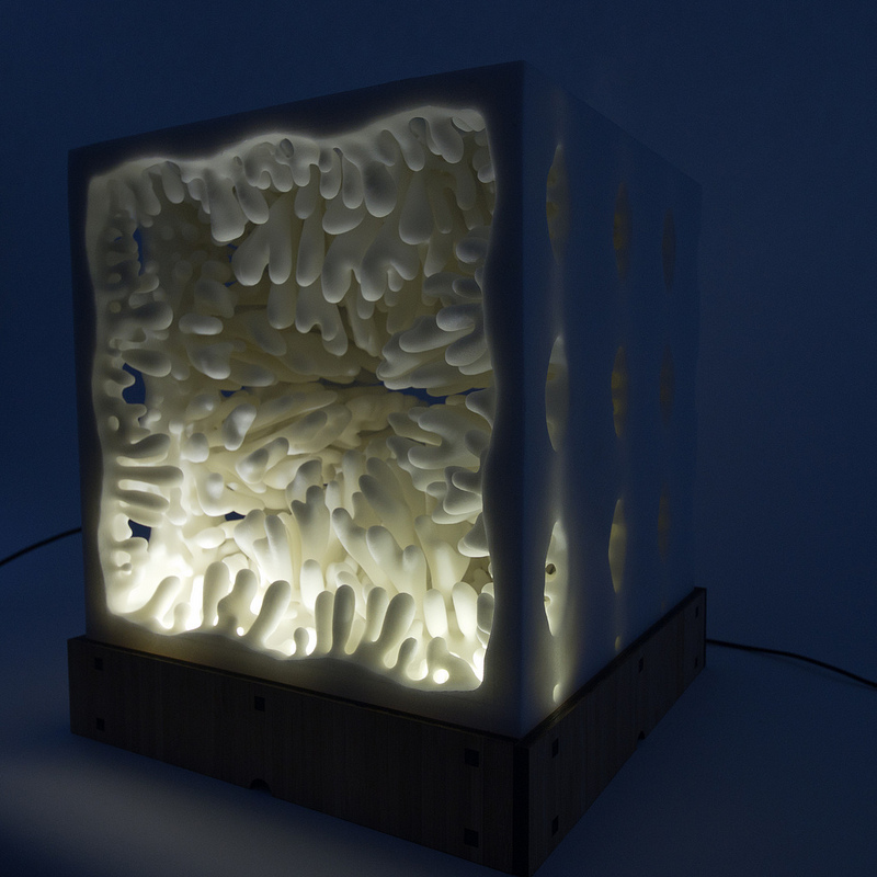
I really, really like LEDs. I’ve spent countless hours building LED controllers, programming them, and incorporating them into my projects. So, naturally, I’ll jump at the opportunity to integrate LEDs into almost anything. Such an opportunity came up when Jesse and Jessica were invited to an innovation event by Nooka and were asked to bring a piece with them. We wanted our piece to be both representative of our normal work, but also a bit more dynamic and eye-catching. So we did the obvious thing: take one of our previously 3d printed pieces, and add some LEDs to it:

The implementation was rather simple. We used 3 Watt ultrabright LEDs with a MOSFET to control them (‘CTRL’ in the schematic) and a series resistor to regulate the current.
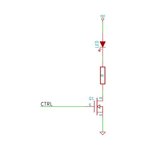
The control signal was created with a Leaflabs Maple microcontroller (we used this instead of an Arduino because it has 16-bit PWM outputs rather than Arduino’s 8-bit PWM, meaning that the lights fade much more smoothly), and we programmed about a half-dozen different patterns into the box. The final result:
One of my side projects has been to improve on the LED circuit we used for this project to make a cheap and durable yet multipurpose driver for lighting up our projects. The goal is for it to be powerful enough to drive ultrabright LEDs for lighting up display pieces, yet easily modified to light up smaller pieces (perhaps even jewelry!). My current design is a simple analog circuit that serves as a constant current source:
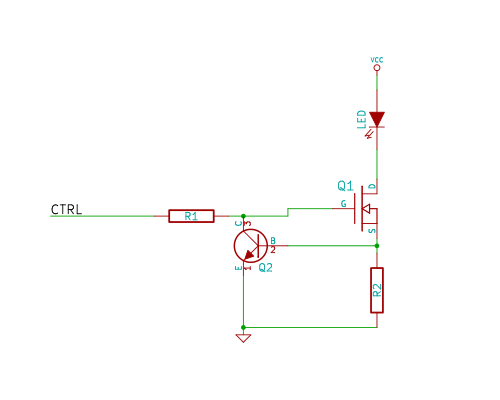
Why all of the additional parts over the first circuit? Superbright LEDs (like those that we used in The Cave) dissipate quite a bit of heat — and this dissipated heat can be enough to damage the LED itself and shorten its lifespan. Even worse, heating of the resistor lowers its resistance, allowing more current flow, creating a positive feedback loop where the circuit just gets hotter and hotter. Not good at all! The solution shown uses a pair of transistors to switch the LEDs on and off (Q1) and stabilize the current with negative feedback (Q2). The current is entirely determined by R2, so by swapping out one component the board can accomodate virtually any LED we’d like to drive. The best part is the low cost — while dedicated LED driver circuits can cost upwards of $3 per chip, this design costs less than $0.25.


Nervous System: Lighting up the world #3dthursday « adafruit industries blog
[…] AND negative-feedback constant-current high brightness LED drivers, what’s not to love? From Nervous System: I really, really like LEDs. I’ve spent countless hours building LED controllers, programming […]
Ron Wooldridge
So perhaps you will be interested in a new type of 3d printing which is the first capable of making optical quality surfaces. Our initial target market is to make optics for LED lighting. See http://www.luxexcel.com.
Nathan Graves
This mechanism is simply awesome.